RX8 Project – Part 6, Canbus #2

So now we have a powered up RX8 cluster and some Canbus hardware that we can talk to we can start doing a few interesting things with our new setup.

Fire up the Arduino IDE and we can start writing our basic controller code. Canbus devices have a device address and a memory location for all the required data so we need to work all of these out. This is a lot easier for digital IO than the more complicated analog values because digital IO are just either set bit on or off whereas analog values can have funny scaling and things going on. I initially used a canbus demo program which worked because I basically cloned the Arduino Canbus shield. Plenty of starter guides and information can be found here : https://learn.sparkfun.com/tutorials/can-bus-shield-hookup-guide

My initial approach involved setting the target address for the Canbus transmission and sending patterns of bits high and low and see what happens. Google told me that the cluster Canbus interface operates on 500 kHz clock so with that information we should get a connection.

#include <Arduino.h>
#include <mcp_can.h>
#include <mcp_can_dfs.h>

#define CANint 2
#define LED2 8
#define LED3 7

MCP_CAN CAN0(10); // Set CS to pin 10

void setup() {
 // put your setup code here, to run once:
 Serial.begin(115200);
 Serial.println("Init…");

Serial.println("Setup pins");
 pinMode(LED2, OUTPUT);
 pinMode(LED3, OUTPUT);
 pinMode(CANint, INPUT);

Serial.println("Enable pullups");
 digitalWrite(LED2, LOW);
 Serial.println("CAN init:");
 
 if (CAN0.begin(CAN_500KBPS) == CAN_OK) 
 {
 Serial.println("OK!");
 } 
 else 
 {
 Serial.println("fail :-(");
 while (1) 
 {
 Serial.print("Zzz… ");
 delay(1000);
 }
 }

Serial.println("Good to go!");
}

unsigned char offarray[8] = {0, 0, 0, 0, 0, 0, 0, 0}; // Always Off Array
unsigned char onarray[8] = {255,255,255,255,255,255,255,255}; // Always On Array

void loop() {
 // put your main code here, to run repeatedly:

for (int i=0; i <= 512; i++){ 
  for (int l=0; l <= 10; l++){  
    for (int j=0; j <= 100; j++){
       CAN0.sendMsgBuf(i, 0, 8,offarray);
       delay(10);
     }

     for (int k=0; k <= 100; k++){
     CAN0.sendMsgBuf(i, 0, 8,onarray);
     delay(10);
     }
   }
  }
}

So this loop will iterate through 512 addresses strobing all 8 bytes high and low on 1 second intervals. The trick here is that canbus needs regular packets to stay active, so we can’t just send a value once. In this case each value (high or low) is send 100 times at 10ms intervals so the cluster should stay active long enough to see if anything is happening. Each address will get 10 cycles of high and low before moving onto the next address. In concept this would work and provided ‘i’ is set to increment high enough you would cover all the addresses. Bear in mind at this rate you’d have to watch it for about 90 mins…

Thankfully around the time I started running though this trying to find any useful addresses I came across this :

https://www.cantanko.com/rx-8/reverse-engineering-the-rx-8s-instrument-cluster-part-one/

This nicely tied in with the hardware I was working on and so the code and information is all exceedingly useful and saved me a lot of time. Specifically it gives the address locations for most of the indicators on the cluster which is what we really need.

After lots of trial and error I managed to come up with a block of code that can control the cluster but easily allow me to set any warning light I need on the dash, or more accurately also to turn off all the warning lights. Something that will be essential come MOT time as a warning light that stays on is an MOT fail and since most of the systems that control them will no longer be in the car (primarily the original ECU).

#include <Arduino.h>
#include <mcp_can.h>
#include <mcp_can_dfs.h>


#define COMMAND 0xFE
#define CLEAR 0x01
#define LINE0 0x80
#define LINE1 0xC0

#define CANint 2
#define LED2 8
#define LED3 7

#define NOP __asm__ ("nop\n\t")

// Variables for StatusMIL
bool checkEngineMIL;
bool checkEngineBL;
byte engTemp;
byte odo;
bool oilPressure;
bool lowWaterMIL;
bool batChargeMIL;
bool oilPressureMIL;

// Variables for PCM
byte engRPM;
byte vehicleSpeed;

// Variables for DSC
bool dscOff;
bool absMIL;
bool brakeFailMIL;
bool etcActiveBL;
bool etcDisabled;


MCP_CAN CAN0(10); // Set CS to pin 10

void setup() 
{
    
    //Serial.begin(115200);
    //Serial.println("Init…");
    //Serial.println("Setup pins");
    
    pinMode(LED2, OUTPUT);
    pinMode(LED3, OUTPUT);
    pinMode(CANint, INPUT);

    //Serial.println("Enable pullups");
    digitalWrite(LED2, LOW);
    //Serial.println("CAN init:");
    
    if (CAN0.begin(CAN_500KBPS) == CAN_OK) 
    {
        //Serial.println("OK!");
    } 
    else 
    {
        //Serial.println("fail :-(");
        while (1) 
        {
            //Serial.print("Zzz… ");
            delay(1000);
        }
     }

Serial.println("Good to go!");
}

unsigned char stmp[8]       = {0, 0, 0, 0, 0, 0, 0, 0};                         // Always Off Array
unsigned char otmp[8]       = {255,255,255,255,255,255,255,255};                // Always On Array

unsigned char statusPCM[8]  = {125,0,0,0,156,0,0,0};                            // Write to 201
unsigned char statusMIL[8]  = {140,0,0,0,0,0,0,0};                              // Write to 420
unsigned char statusDSC[8]  = {0,0,0,0,0,0,0,0};                                // Write to 212

unsigned char statusEPS1[8] = {0x00,0x00,0xFF,0xFF,0x00,0x32,0x06,0x81};        // Write to 200 0x00 00 FF FF 00 32 06 81
unsigned char statusEPS2[8] = {0x89,0x89,0x89,0x19,0x34,0x1F,0xC8,0xFF};        // Write to 202 0x89 89 89 19 34 1F C8 FF

unsigned char statusECU1[8] = {0x02,0x2D,0x02,0x2D,0x02,0x2A,0x06,0x81};        // Write to 215 - Unknown
unsigned char statusECU2[8] = {0x0F,0x00,0xFF,0xFF,0x02,0x2D,0x06,0x81};        // Write to 231 - Unknown
unsigned char statusECU3[8] = {0x04,0x00,0x28,0x00,0x02,0x37,0x06,0x81};        // Write to 240 - Unknown
unsigned char statusECU4[8] = {0x00,0x00,0xCF,0x87,0x7F,0x83,0x00,0x00};        // Write to 250 - Unknown


/*

215 02 2D 02 2D 02 2A 06 81 // Some ECU status

231 0F 00 FF FF 02 2D 06 81 // Some ECU status

240 04 00 28 00 02 37 06 81 // Some ECU status

250 00 00 CF 87 7F 83 00 00 // Some ECU status

*/


void updateMIL()
{
    statusMIL[0] = engTemp;
    statusMIL[1] = odo;
    statusMIL[4] = oilPressure;
    
  if (checkEngineMIL == 1)
  {
    statusMIL[5] = statusMIL[5] | 0b01000000;
  }
  else
  {
    statusMIL[5] = statusMIL[5] & 0b10111111;
  }
   
    if (checkEngineBL == 1)
  {
    statusMIL[5] = statusMIL[5] | 0b10000000;
  }
  else
  {
    statusMIL[5] = statusMIL[5] & 0b01111111;
  }

   if (lowWaterMIL == 1)
  {
    statusMIL[6] = statusMIL[6] | 0b00000010;
  }
  else
  {
    statusMIL[6] = statusMIL[6] & 0b11111101;
  }

     if (batChargeMIL == 1)
  {
    statusMIL[6] = statusMIL[6] | 0b01000000;
  }
  else
  {
    statusMIL[6] = statusMIL[6] & 0b10111111;
  }

       if (oilPressureMIL == 1)
  {
    statusMIL[6] = statusMIL[6] | 0b10000000;
  }
  else
  {
    statusMIL[6] = statusMIL[6] & 0b01111111;
  }
}

void updatePCM()
{
    statusPCM[0] = engRPM;
    statusPCM[4] = vehicleSpeed;
}

void updateDSC()
{       
  if (dscOff == 1)
  {
    statusDSC[3] = statusDSC[3] | 0b00000100;
  }
  else
  {
    statusDSC[3] = statusDSC[3] & 0b01111011;
  }

    if (absMIL == 1)
  {
    statusDSC[4] = statusDSC[4] | 0b00001000;
  }
  else
  {
    statusDSC[4] = statusDSC[4] & 0b11110111;
  }

      if (brakeFailMIL == 1)
  {
    statusDSC[4] = statusDSC[4] | 0b01000000;
  }
  else
  {
    statusDSC[4] = statusDSC[4] & 0b10111111;
  }

     if (etcActiveBL == 1)
  {
     statusDSC[5] = statusDSC[5] | 0b00100000;
  }
  else
  {
    statusDSC[5] = statusDSC[5] & 0b11011111;
  }

    if (etcDisabled == 1)
  {
    statusDSC[5] = statusDSC[5] | 0b00010000;
  }
  else
  {
    statusDSC[5] = statusDSC[5] & 0b11101111;
  }
 

}

void loop() 
{
    // StatusMIL
    engTemp         = 145;
    odo             = 0;
    oilPressure     = 1;    // Either 0 (fault) or >=1 (Ok)
    checkEngineMIL  = 0;
    checkEngineBL   = 0;
    lowWaterMIL     = 0;
    batChargeMIL    = 0;
    oilPressureMIL  = 0;

    updateMIL();
    CAN0.sendMsgBuf(0x420, 0, 8, statusMIL);
    delay(10);


    // StatusPCM
    engRPM          = 60;    // RPM  Value*67 gives 8500 RPM Reading Redline is 127
    vehicleSpeed    = 93;    // Speed  Value=0.63*(Speed)+38.5

    updatePCM();
    CAN0.sendMsgBuf(0x201, 0, 8, statusPCM);          //CAN0.sendMsgBuf(CAN_ID, Data Type (normally 0), length of data, Data
    delay(10);

    // StatusDSC
    dscOff          = 0;
    absMIL          = 0;
    brakeFailMIL    = 0;
    etcActiveBL     = 0;    // Only works with dscOff set
    etcDisabled     = 0;    // Only works with dscOff set

    updateDSC();
    CAN0.sendMsgBuf(0x212, 0, 8, statusDSC);
    delay(10);

/*
    CAN0.sendMsgBuf(0x200, 0, 8, statusEPS1);
    delay(10);            

    CAN0.sendMsgBuf(0x202, 0, 8, statusEPS2);
    delay(10);    
           
    
    CAN0.sendMsgBuf(0x215, 0, 8, statusECU1);
    delay(10);  

    CAN0.sendMsgBuf(0x231, 0, 8, statusECU2);
    delay(10);  

    CAN0.sendMsgBuf(0x240, 0, 8, statusECU3);
    delay(10);  
    CAN0.sendMsgBuf(0x250, 0, 8, statusECU4);
    delay(10);  

*/
            
 }

This is the current latest version of the code I have, the serial comms section at the start is handy for checking you have a working connection but if you don’t have the serial monitor open it will cause the Arduino to hang at the transmit instruction and not get as far as updating the canbus so I recommend enabling these initially but once you get a working connection comment them back out as above. There are also sections above taken directly from the Cantanko page to deal with the power steering controller and some other bits, I haven’t tried these yes as the cluster isn’t in a car but I plan do so at some stage.

This code has some limitations in this form, basically the warning lights etc are set in the code as static values so this code will just set everything normal and all the lights I have addresses for to off. One particular curiosity is the way the cluster treats the oil pressure value. The data space actually has a whole byte for a value here but the cluster only only has two values despite having an actual gauge, a value of 0 drops the needle to the bottom, a value of 1 or more sets the gauge to normal. My feeling on this is the car was originally intended to have a proper oil pressure transmitter but someone decided it was too expensive and a normal pressure switch was used instead and rather than redesign the cluster they just changed the scaling in the on board microcontroller to behave as described. long term I’d love to mod the cluster to add the analog functionality back in but without the code for the controller this would probably involve disconnecting the original drive to that gauge and adding another Arduino inside the cluster just for driving that gauge. It seems like a lot of work to know oil pressure on a scale of low to high!

The code also sets a speed and RPM however the ODO and trip meters will not increment as it stands – I purposefully left this bit of code out because it’s only really applicable if you’re on an actual car otherwise your cluster will just keep clocking up. The ODO and trips seemed to be the one bit no-one else had managed to do or identify but after quite a few hours of testing  random blocks will various combinations of high and low as well as sending incrementing / decrementing values I noticed my trip meter had actually moved up by 0.1 miles which meant something was working. I eventually managed to trace it to the address listed above. The trick to actually making it work is that the value in the byte is irrelevant to what the cluster displays, so no this doesn’t let you clock it back! What it appears to do is counts the changes to the value so I made it work by setting up a loop of code that keeps changing this value up to a certain number to give a specific distance. Turns out the cluster needs to see 4140 changes per mile. Eventually I plan to tie this in to the speedometer value so only one value needs to be set, by knowing the pulses per mile and the speed we can work out the time delay between each change. As an example at 100mph we need to send 115 changes per second, this is one every 8.7ms which is obviously faster than the loops above and so for speed and accuracy would have to be hardware timed with an interrupt to do the update at the right speed. I’ll probably do an updated version at a later date.

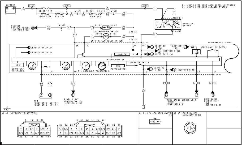
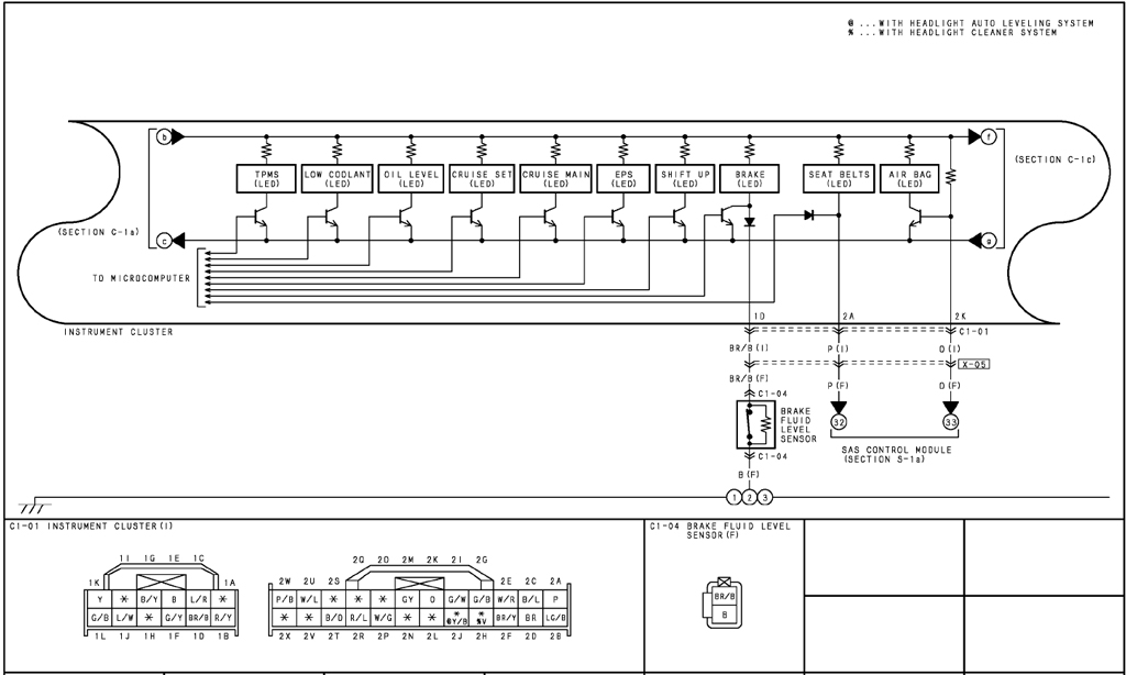
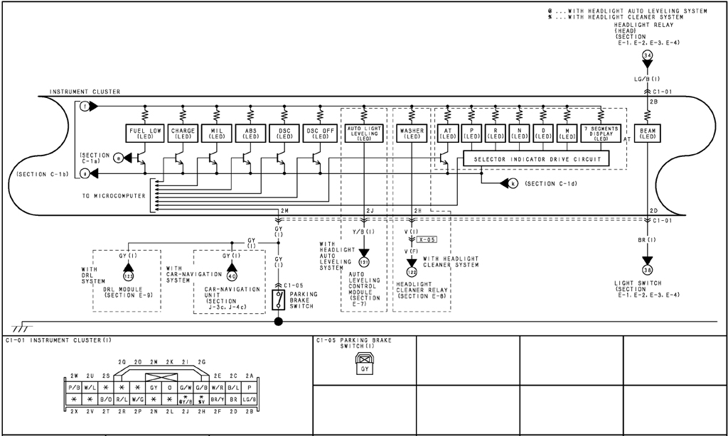
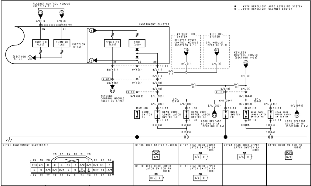
There’s a couple other things I need to sort out, the airbag warning light being the prime one because this is an outright MOT fail. Now in theory when it’s back on the car it should work just fine as the airbag wiring is all there but I figured it was worth working out anyway. So after working through all of the RX8 cluster wiring diagrams (1)(2)(3)(4) I pieced this together :RX8 Cluster Pinout

This covers the majority of everything someone might need to use the cluster on a simulator apart from the fuel gauge. The RX8 fuel gauge is a bit of an oddity because the car uses a saddle shaped fuel tank to allow it to clear the driveshaft and so it has two senders denoted as ‘main’ and ‘sub’.

RX8 Fuel System Senders

Each of these apparently has a resistance value of between about 325Ω at the bottom and 10Ω at the top. There seems to be some questions about how this system works out what to display based on the two sender values and whether it expects to see one remain full while the other empties or something similar. Unfortunately I’ve not played with it much because I’ve don’t actually need to make this work off the car (since the car will have the senders but I can say putting 100Ω a resistor between both 2R-2P and 2R-2T gives a value of about 1/3 of a tank and 9Ω (because I just added a 10Ω on along side the existing 100Ω) across these connections gives a full tank reading  (actually a little above full) so as long as you move both together it works fine, this is ok if all you want to do is get the fuel warning light off for a driving simulator but not that helpful for a single fuel sender conversion which is why most people are interested. If I get chance I’ll investigate further. Also for some reason it takes an absolute age to move up the scale which is a bit unfortunate but I suspect is as intended. At least it should be stable!

All of that leaved us with just one light I can’t get to turn of, the warning light for the electronic power steering. This is controlled via canbus by the look of the circuit diagram but as yet I’ve not found the address for it. If anyone knows the address please leave a comment! Else I will have to go back to either trial and error or the really dodgy backup plan which involves cutting the tracks in the cluster and doubling up on another warning light which isn’t used much! Maybe I should just add another controller in the cluster!

So hopefully that gives you (almost) everything you need to know about making the cluster work! We might get back to mechanical things in the next update…

RX8 Project – Part 5, Canbus

Following the decision to go for the complete engine swap I had the sudden realisation that nothing was going to work on the car because I wouldn’t have the factory engine and so also wouldn’t have the factory ECU and so no engine data and nothing on the instrument cluster. So I needed to come up with a better plan!

Initially I intended to open up the stock instrument cluster and replace the normal controller circuits inside the cluster with a microcontroller (probably an Arduino) with suitable supporting electronics such as motor driver IC’s to control the gauges and small MOSFET’s to switch the warning lights and anything else I needed to get it working. Done in that way I could interface almost anything to the Arduino and make the cluster behave however I wanted.

I started looking into what wiring the cluster had normally to see if I could hack into anything directly and not have to fake signals, say a nice direct tachometer connection I could use, but found that virtually everything on the cluster was controlled via a canbus communications connection and this gave me other ideas.RX8 ClusterFor anyone who doesn’t know canbus is a differential communications interface used in the majority of common cars to connect all the separate devices together. It is what’s called multi drop and as such all the devices are basically just daisychained on a single pair of wires. Complexity is the data is sent to a specific target device based on a device ID which we don’t know and the format the device needs the data in is to give a particular result is entirely up the manufacturer. So for example even if you found the memory location that controls RPM it might be using a single byte (256 possible values) to represent RPM in the range of 0-7500 rpm. This means that each increment would be a step of approximately 30 rpm which would likely not be noticeable. Or they might use two bytes at different addresses which combine to give the value, or something more complicated! Figure it all out and you can directly control the cluster!

The Arduino can be made to communicate with a canbus system with appropriate components added on. These are available as an off the shelf canbus shield and if you’ve not build circuits like this before I recommend that approach but since I have an electronics background I decided to DIY my own and save the money and so I started down the route of designing a canbus interface. I then had another interesting thought, if I had an engine ECU for the new engine it would be transmitting all sorts of data about what it was doing which would normally go to the cluster of the car it was from. I could work out what address it was sending that data too I could read it all. So suddenly one canbus interface grew to a pair of them so I could connect one to the engine ECU and one to the cluster and eventually use the pair of interfaces to bridge the two canbus connections and convert and reformat all the engine data in real time to control the cluster. Sounds simple right!

Based on information found via Google the chips to use seemed to be the MCP2515 transceiver and MCP2551 canbus line driver. Part of the reason behind this was there are well documented libraries available for the Arduino to work with these, plus they are available in DIP packages to make prototyping on stripboard easier!

Sadly I can’t seem to find the original circuit diagram I drew for this but it was closely based on this one (click to enlarge):Arduino MCP2515 Interface

I tend to use Arduino nanos in my projects, they are very small but have a good clock speed and all the handy features you’re likely to need for fairly small IO count projects. Plus you can buy the knock off version on eBay for very little, my last ones were 5 for £12 delivered next day but can be had for less if bought from a Chinese seller but obviously with a much longer delivery. The down side of these is they make them cheaper by not using the proper FTDI branded USB to serial converter chip, instead they use the CH340G which means the driver isn’t included with the normal Arduino IDE and must be downloaded and installed manually. The appropriate driver can be found from a number of sources via Google.

After quite a bit of work I ended up with something that looked a bit like this (ok, exactly this!)

Arduino Canbus adapter top Arduino Canbus adapter bottom

The red and black coloured solder lines are to distinguish the 5V power from the Arduino from everything else to make sure I hadn’t accidentally shorted  it out. Needless to say there’s quite a bit going on on the bottom of this board! The converter board has options for either screw terminal connectors or the 9 way DSUB used for certain applications. I’ve also included options for connecting power into the DSUB if required. On particularly important feature is the termination resistor, this is situated next to the blue jumper, moving the jumper turns this on or off. Canbus must have this termination resistor connected between the two bus wires (called CANL(-) and CANH(+)) at each end of the bus, so if this is an end node on the bus it needs enabling. If it’s being added to the middle of an existing bus it should be disabled. Other keen people will notice there’s only one Arduino slot occupied, this is because by the time I took the photo it had been commandeered for another project but since I was still working with identifying signals in a single bus at a time it didn’t really matter. I did initial test with two Arduinos connected via canbus  with one transmitting and one receiving just to prove the hardware out.

Next up we need to connect the new hardware up to the RX8 cluster. This assumed it is disconnected from the car, if it isn’t you won’t need to tie in power to the cluster but I have no idea how the but will behave in this situation. If you experimenting as I am it’s advisable to disconnect the canbus pins to avoid problems or just disconnect the whole cluster. to make this work we need to use the smaller connector on the back only. In the diagram above you can see the pinout for this, the simple version is :

Upper Row going left to right
Spare
Spare
B/Y – Ignition Switched +12V
B – 0V (PSU Minus)
L/R – Permanent +12V
Spare

Lower Row
G/B – CANL
L/W – CANH
Spare
G/Y – Unknown
BR/B – Unknown
R/Y – Unknown

For testing purposes both +12V can be connected together and any normal 12VDC PSU (cheapo wall wart or anything else you have) can be used. Congratulations, you now have a powered up cluster you can work with!

Things will get technical in the next section Canbus #2

RX8 Project – Part 4, The New Engine

Following part 3 where the original rotary engine proved to be a lost cause I decided to research possible engines  that could be swapped in but there were a few criteria and limitations I had:

Size – The RX8 has a reasonable size engine bay overall but due to the size and position of the standard engine there are some limiting factors to consider. I’m aware others have swapped V8’s (among others) into RX8 shells but this generally involves extensive modification of the engine bay, steering rack and even front cross member due to the length of the engine.

Weight – The RX8 is famous for being very balanced largely due to the compact size and resulting low mounting position of the standard engine. No standard piston engine will quite match up but I wanted to get as close as reasonably possible.

Power – The standard RX8 was available with either 192 or 231 bhp and so I wanted to get to ideally the upper figure (even though mine actually started as the lower 192 model) or even exceed it if possible.

Cost & availibility – I wanted  and engine that was cheap to buy and for which spares were cheap and readily available. This was always intended to be a budget project to swap the engine more cheaply than replacing it.

After considering a huge number of options from things people have done before (VW 1.8t engine) to completely off the wall ideas that would probably upset all the RX8 purists (1.9 turbo diesel?) I eventually came across a couple really  promising candidates – the Mazda KLDE and Ford AJ series engines. These are both very compact aluminium construction V6’s which should be short enough that no modification to the front cross member should be needed. It became apparent pretty quickly that the KLDE was hard to find and attracted a comparatively high price so I ruled this out.

The AJ V6 is related to the older KLDE and is available in a few flavours. It was produced as the AJ25 and AJ30 (2.5 and 3.0 litre respectively) and were used in a a range of cars in slightly different configurations including the Ford Mondeo ST220 (along with US Contour and Taurus), Jaguar S-type and X-Type along with several others. Some (including the S-type version) have VVT.

S-type V6
S-type V6

So after an eBay search and a hard earned £165 (including delivery) later I had this prime example of an AJ25 from an S type Jag sat on my driveway. At this stage I went for the 2.5L because the 3.0L version attracts a more premium price and since I had no real idea if it I would ever get it all together I bought the cheap version. Since the block is identical for both the logic was if I made one fit and decided I just didn’t have enough power I could swap all the custom parts over to a 3.0. Clearly there’s a lot of extraneous parts on here I won’t be using and once much of this is stripped the true compact size of the engine is a bit clearer.

Stripped AJ25
Stripped AJ25

There are a few reasons I picked this version of this engine. One was that the Mondeo version, which is more common, has the water pump driven from and extended camshaft on the rear of the engine because in the Mondeo the engine is in a transverse orientation. To fit the engine to the RX8 the engine will need to be installed longitudinally and the rear will have to be very close to the firewall so this is a non-starter. The Jag version has the water pump front mounted so avoids this problem. The Jag version also includes direct acting mechanical bucket cam followers and VVT. Sadly the 2.5L generally only offers 200bhp in this configuration so it’s a little down on where I really wanted to be but the torque is 240 Nm compared to the 211 Nm peak of the 231 bhp RX8 and a considerably wider torque band so it should still go well.

Around this time I found out that the Noble M12 uses this same 2.5L engine running as a twin turbo at 325 bhp. The later M400 uses the 3.0L version of the engine but they again two turbos to it and get something in the order of 425 bhp out of it with minimal additional modifications. Reports from Noble suggest it is capable of even more but was limited because they were planning on upping the power later selling this as  another model but due due to the change of direction and ford taking the engine out of production this never happened. More info can be found here : Noble M12 History

I also made the decision to keep the RX8 gearbox so I could retain the standard carbon prop shaft in the RX8 so next up is the challenge of making an engine made by Ford, which was salvaged from a Jag, fit the gearbox from a Mazda!

More in part 5…

RX8 Project – Part 3, Engine Autopsy!

Rather long delay since the last post on this project mostly due to a server problem it took a while to resolve.

So here it is, the autopsy of a failed RX8 engine. First here’s how the engine looks freshly removed from the car.

RX8 13B Engine
13B Engine Complete
13B-Left Side
13B-Left Side


The 13B rotary engine really is rather small and while it is true to say it is a comparatively light engine (I’ve heard figures around 130kg though I’ve not checked this) it is a solid lump with very little space inside. It’s also worth noting the four spark plugs at this point – this engine has leading and trailing plugs and actually fire the chamber twice during combustion phase which is a little unusual for an engine.

13B Engine stripped to core
13B Core

Here’s the next stage, strip all the supporting components from the engine. So the alternator, aux drive belt, manifolds, ignition coils, clutch and anything else bolted onto the main block.

13B Stripped Components
All the bits removed

So when you get to this point you will (if you haven’t already) realised the flywheel must be removed to break down the engine any further as the engine is built as a series of layers with long through bolts. These through bolts are all located under the flywheel hence why that needs removing.

13B Flywheel
13B Flywheel

The bad news here is that the flywheel is held on by a single very large nut, this nut is 54mm across flats. I have no idea what torque it is tightened to, but it’s very tight, very fine pitch and is installed with thread locker adhesive.

The first problem is locking the engine solid. I actually  used a section of steel between two of the the clutch bolts and then another bolt through one of the bell housing bolt holes. Obviously the steel must be installed across two bolts so it doesn’t cross the nut you’re trying to remove. Alternatively proper locking tools can be bought but the ones I could find were quite pricey. As for the actual nut I ended up buying a 54mm impact socket which on its own was about £30.

54mm Socket Vs Pint Glass

For the actual removal I tried a long 1/2″ breaker with a big cheater bar and ended up shearing the end off the bar! The bolt didn’t budge! I ended up convincing a mechanical fitter where I worked who was well into cars to stay a little late one night, borrowed the company van to get the engine up to the workshop and borrowed his largest 1/2″ drive air impact gun to remove it. After a bit of an argument the nut eventually moved!

13B with flywheel removed

Next I took off the sump, while I could have done this earlier I was largely resting the engine on the sump so it made sense to leave it in place. This moment was a huge warning of what was to come!

Very contaminated oil
Oil/Water!

So, apparently this was once oil! Judging from what came out it was something like 90% or more water at this stage suggesting a serious internal failure of a water seal. This is a known problem in these engines and if caught early is repairable. In this case unfortunately the engine had still been used for some time after the warning signs started appearing with the previous owner running the car until it wouldn’t idle at all or restart when warm. Expectations for the engine were not high at this point!

It’s worth pointing out at this stage you need to find a way to prop up the engine vertically to disassemble from the flywheel end. Again a guy at work helped me out here by building me a custom engine stand from offcuts in a quiet moment but other solutions could be used. the positions I used were the rear pair of air con mounts.

Seriously rusty rotor
Well that doesn’t look good!

On opening it I was met with this sight. Again this confirms very large amounts of water getting inside the engine. Several parts of the engine are cast iron and so will rust for a pass-time when exposed to water. Add to that the total lack of lubrication offered by the water and engines will basically overheat and the bearing surfaces will eat themselves alive.

Badly damaged rotor bearing

Notice the scoring on the internal bearing surface on this rotor.

E-Shaft Heat Marks
E-Shaft Heat Marks

Here is the lobe on the eccentric shaft that the rotor locates on. This photo clearly shows the the lobe has experienced excessively high temperatures to such an extent the shaft has discoloured.

Damaged E-shaft
Damaged E-shaft

And the final shot shows the amount of scoring on the shaft. Clearly everything is not well.

13B O-Ring Failure
13B O-Ring Failure

So this is what actually caused the damage. These o-rings seal both the water from the combustion chamber (red) and from the outside world (black). As can clearly be seen in the photo the outer seal has degraded to the point of failure. The really unfortunate aspect here is is this seal failed at any point over most of its length the engine would leak coolant but this wouldn’t actively damage the engine. What happened here is the point of failure was above the sump so as the water leaked out it filled the sump with more water than oil progressively ruining the engine. The inner seal in this engine had also failed and this means that once the coolant is hot and under pressure it leaks into the combustion side. This is a common cause of the warm idle and restart problems.

More signs of running without oil - chatter marks in the housing
13B Housing damage

So this was the final nail in the coffin for this 13B engine, both rotor housings were ruined with significant chatter marks, scoring and chipping of the hard chrome surface and these cannot be restored because the only people that have a specialist surface grinder to finish the hard chrome surface in the correct profile is Mazda. So at this point virtually everything needs replacing, effectively this is buying a new engine and costs a huge amount of money. for a £300 car it just isn’t worth it.

So now project moved onto what reasonably priced alternative engines could be fitted for less than the cost of replacing the proper engine….

More in part 4!

RX8 Project – Part 2

In part two we look at finally getting the engine clear. In reality due to the time I had available this process actually took something like three months. A qualified professional mechanic can remove the engine in an RX8 in as little as three HOURS! Clearly I’m not a professional mechanic!

I didn’t fully document the process as there are any number of people who have already done excellent write ups of this but hopefully I can offer a couple of pointers to anyone trying to do this. Officially the engine should be removed by dropping out the front sub-frame and not being able to do this easily on a driveway has led me to removing the engine upwards. This adds a few minor problems along the way but nothing insurmountable

One thing I found is that you really need to remove the crank pulley to clear the front crossmember. While you probably could yank it past regardless it makes the process notably easier.

RX8 Crank Pulley
RX8 Crank Pulley

With somewhat awkward visibility it can be hard to tell whats going on but it looks like this. You do not need to remove the main bolt – the pulley is just held on by the four small bolts around it (already removed in the photo).

The next major problem is removing the engine mounts. I found it virtually impossible to get at in any conventional way. You can get a ratchet on but they’re quite tight and there’s little room, and a breaker bar doesn’t have room to move. My solution to this was to undo the bolts from the top of the engine bay with a selection of extensions. These need to be 1/2″ drive as my 3/8″ drive ones were starting to flex a bit plus you will probably need a breaker bar. Due to the angle restriction a UJ is also required. While the whole assembly looks a bit bodged it works fine.

RX8 Engine Mount Removal

Also the oil line connectors, these are really awkward and are usually corroded solid. Hose them liberally with WD40 and let it stew overnight if they are a problem. If you plan to use them again don’t lose the small retaining wire ring, these can be hard to replace (though can probably be replaced by a snap ring from an engineering supplier).

After another brief pause for another project we started watching some car based youtube videos (Roadkill and Mighty car mods for anyone interested) and after feeling inspired to do car-ish things and pull the engine out.

RX8 Engine Bay Night

My best advice on this one is – don’t try to remove an engine when it’s dark and drizzling!

RX8 Engine Out
RX8 Engine Out

Next up, rotary engine autopsy! Coming soon!

RX8 Engine Swap Project Intro

So the RX8 project involves making what is effectively a worthless vehicle useful again. For anyone not familiar with the Mazda RX8 they are a fairly high spec 4 seater car which is most widely known because it uses a Wankle rotary engine. This type of engine does not use pistons and so is incredibly smooth in operation and in the higher power (231) version of the car revs to 10,000 RPM as standard.

Sadly for all its good points the engine has a number of down sides. In terms of behavior the engine shares a number of similarities to a two stroke piston engine, one aspect is that it is designed to burn oil in normal operation to such an extent it actually has mechanical components to inject oil into the combustion chamber. This means the oil needs to be topped up frequently and it is recommended to check it every time the fuel is filled, though this isn’t as easy it probably should be and very few people do so. As a result many engines fail rapidly due to lack of lubrication once the oil gets low.

The other common failure is with the o-rings which seal the sections of the engine to each other if these fail water gets into the combustion chamber when the cooling system is under pressure (i.e. once the engine is hot). This is one common cause of the warm start/idle problems and where water gets into the oil you get lack of lubrication failure eventually as well.

The engines are expensive to get repaired assuming the fault is detected early enough and no major damage has occurred. If major damage has occurred then sections or even the whole engine may need replacement. Either way the repair is likely to cost more than the car is actually worth and this seems to happen at something around 60-80,000 miles. The combination of all of this is that these cars are abundantly available for very little money with engines in  varying degrees of failure but with relatively few miles on the clock. This leads us nicely to exhibit A:

Cheap RX8
Cheap RX8

This is a 55 plate RX8 I bought from ebay for grand total of £300 taken on the day I bought it in July 2015. While technically still road legal at this stage the car wouldn’t idle when warm so was not drive-able for any real distance without serious difficulty. In order to collect it I had to impose on a friend who has a van and car trailer for moving his racing car.

My plan for the car was to remove the engine and dismantle it to see how far gone the internals were and if possible repair the engine and reinstall it. Failing that the backup plan was to try to swap in an engine from something else simply because buying a working replacement rotary engine would cost approximately £3500!

So having got the car home the next day we started taking things out:

This may look a little unconventional but in the UK the RX8 was Thatcham security rated. Part of this involved preventing the ECU from being removed because otherwise any wannabe car thief could just swap the ECU for one from a scrap yard for which they have the matching immobiliser chip, then either hotwire it or force the ignition lock like older pre-immobiliser cars. RX8’s from other countries do not have the steel retaining plates as they do not have this rating. Since the retaining bars (gold in the picture) were several mm thick and held in place with any number of rivets the only option (well the only one we could come up with at short notice) was to drill the rivets outs. I recommend centre punching (creating a divot in the centre) the rivets before drilling because they are domed and the drill will skid off. Now technically you could probably remove all the plugs on the engine and leave the ECU in place but we wanted to allow as much room as possible to take the engine out.

Unfortunately in the RX8 the engine is mounted very low and well back with a lot of ancillaries on top of it making removal a little more time consuming:

RX8 Engine Bay
There’s an engine in there somewhere!

Incredibly the back end of the engine is nearly level with the visible firewall and the front is indicated by the alternator! Yes is really is a very small engine and this particular one is the lower power RX8 – so the output of this engine is *only* 192 bhp!

RX8 Engine bay end of day 1

And this was basically where we got to by the end of our first day removing parts. In truth this is only about three hours in as we’d had something of a heavy night and bright sunlight wasn’t helping the situation!

More to follow shortly…

Finished Pipe Vice

So I finally finished the pipe vice seen in a previous post after getting distracted by other projects. I actually needed to use it for its intended purpose which is something I never fully expected when I started restoring it. I needed to tap a thread into a section of bar as part of another long term project (involving a Mazda RX8 – soon to be added to this blog).

Somewhat appropriately the first time I used it again after putting it back together would have actually been my granddads birthday. Asking around the family by best estimations this vise was purchased for installing pipework when my granddad built his house some 55 years ago. With any luck it will last another few decades!

Anyway, here it is :

Finished Pipe Vise
Finished Pipe Vice

Old Houses!

So having started putting information on here there has been something of a gap in progress to to various other projects getting in the way, a problem I’m sure others will sympathise with!

On thing that’s been keeping us all busy of late is our house (which is a very old ex pub) appeared to have something of a woodworm, nothing too serious but a problem we wanted to rectify while we still had as little stuff as possible to do any harm to! Anyway the outcome of this was we needed to treat the entire attic and first floor meaning we had to remove all of the floorboards on the first floor and clear all the attic space, in total something like 200m², so let the chaos begin!

So the story begins with dust, not just any dust but the sort of residue you get after a building has been left for upwards of 200 years, this stuff is awful, if you have have to deal with it you’ll understand what I mean! It WILL get everywhere, I’ve previously used those cheapo disposable masks and have found that while they more or less work as soon as you start moving about a bit they either fall off or lift away from your face enough to leak and not do anything. My feeling on this is if you ever have to do anything like this it’s worth splashing the cash a bit on a half decent one. Personally I bought 3 of these : http://www.screwfix.com/p/site-reliance-28-day-half-mask-respirator-ffp2/1232j
T
hey seemed to fit well as they are flexible rubber and have replaceable filter elements. There are plenty of other options that should also be fine, out of preference I would just avoid the cheapo ones. This was around the time we realised the better masks were a good idea.

dust
Dust!

Adding to the above, safety goggles! When you start ripping apart a building things will start flying, be they intentional or not! In our case we had to add a new loft hatch to one end of the building to allow access. the building being rather old and actually still has old style plaster and lath. This is where lots of small sticks are nailed onto the beams and the plaster would be pressed through between the sticks where it will curl round the back of them and set holding the plaster in place. This works very well if left untouched but sadly it’s rather fragile if it is ever disturbed the back half separates from the front and the plaster peels off the ceiling! The problem here being if you start cutting through it you will get covered in an torrent of plaster, horrible black dust, splinters, nails and anything else that’s previously been left all over the attic. We had big lumps plaster, concrete and even daub (as in wattle and daub)! Goggles are not just a good idea in this case, I rank them as essential! This is a chunk of daub we found in the attic, it’s about a foot wide…Admittedly if this fell on you goggles would only help to a limited degree!

Daub
Daub

So now next up we had two old galvanised steel water tanks up there that were long since taken out of use. Somehow, I’m not sure how, the tanks were about double the size of the hatch we had to get them through. The obvious answer to this was to make the tanks half the size! So knowing this I got tooled up and got to it. First off I tried a 4.5″ angle grinder, while it kind of worked sparks flew everywhere as expected and after cutting 6 inches or so the first cutting disk was gone. If you ever try this I recommend having a second person to hand with a fire extinguisher. you will also need plenty of cutting disks, or ideally a larger diameter grinder may work better! After my first disk I abandoned the grinder and went for a reciprocating saw, specifically this one. These are a very aggressive tool but highly effective. To be honest on these it was like a (very noisy!) hot knife through butter. In total for the two tanks I wore out one already part used blade, bent a second one that it turned out I had previously ruined and had to do the last couple inches with a new one – In hindsight I should’ve just started with the new blade!

So back to ripping up the floor, just as a quick example of what chaos we’re talking about here, so this is the master bedroom as :

Is it still the first floor if it doesn't actually have a floor?
Floor-less bedroom

And here’s another bedroom, after insulation was installed in the floor. In most houses this really isn’t necessary but in this case it has quite a few benefits. Firstly being an old building it has a lot of drafts from pretty well everywhere, there are large gaps around sections of the floor allowing all the warm air from the ground floor to escape upstairs, plus any noise passes right through.

Bedroom 1 Floor
Bedroom 1 Floor

Hopefully that will solve a lot of these problems, we also packed felt sleeving (I bought some of this, it comes as a tube which isn’t ideal but it can be cut open or if the pipes are really close just wedged between them pressed flat as a double layer between to stop them clanking as they change temperature.

Anyone looking at this and thinking  there’s a lot of pipes and cables in there, you’re right! Being an ex-pub everything is wired separately so we have quite a lot of individual sockets which have their own circuit breakers and other related things which would be excessive in a house but in a business where you don’t want one faulty appliance to trip out all the power it becomes worth the additional cost and effort!

The other thing we’re working on is adding a networking cupboard to tidy up all of our wiring and to add a number of wireless access points to have internet all over the building. Being old and stone construction wifi doesn’t exactly travel far so we need to do something a little more serious than the average wifi router! I suspect that’ll be another blog another day!

Refurbishing Vises

Another of the things I was given by my granddad was some well used Record branded vises, specifically a type 23 engineers vice, a type 91 pipe vise and a type 52 woodworking vise. All of these had clearly had quite a lot of use in their lives but were still functional. Unfortunately they clearly hadn’t had any attention for a number of years and just needed a bit of tlc before they started their new life.

Yet again I’ve decided to do it properly. The first step was to remove all the grime, there was old grease, loose paint and quite a lot of surface rust so I went to it with a powerdrill fitted with a rotary wire brush.

Vise

This removed the majority of the grime but I needed to use a solvent to degrease the surface prior to painting.

Degreased Vise

It’s probably worth pointing out at this point that due to me wanting to try out the new paint I didn’t clean the entire vise, that’ll have to wait for another day.

The key bit for me of restoring these vises was making them look the part, so while I could have painted them any colour I did quite a bit of research and found the correct factory original colour for them is BS381C-110 Roundel-Blue. I managed to find one place who could supply a this as a very high quality enamel paint – Paragon Enamel Paints it can be bought via Ebay or direct from their website. I’m not going to lie, it’s not exactly cheap but even the smallest 0.5l can goes a surprisingly long way so you can always retouch it if you need to. It’s also worth pointing out at this point that they specify PT8 synthetic thinner as there doesn’t appear to be much that works. I recommend buying this with the paint as it’s probably the best option for cleaning brushes/spills – sadly me being me it hadn’t noticed this and just cleaned the brushes with petrol.

Painting in progress

Now having painted half the first vise I realised that while I was waiting for it to dry I couldn’t clean the other side. I admit that was obvious but I wanted to see what the paint looked like! So I started looking at the next vise:

Type91

This is a type 91 pipe vise is generally used for holding a pipe or tube usually to cut a thread onto the end without crushing it. Such fittings used to be used for water pipes in houses many years ago but that is no longer the case but threaded pipes and rods are still widely used in engineering.

wp_20160831_20_03_29_pro

This time I disassembled the threaded bar to avoid potentially getting paint on it as well as some other moving parts and all three jaws. I then cleaned it in the same way as the other vise – although with the addition of of a toothbrush to get into some of the corners.

wp_20160903_11_30_07_pro

Next up was painting it, this one was a little more fiddly as it wasn’t attached to anything – in retrospect I probably should have just screwed to to a bit of wood but hindsight is a wonderful thing! Also It has a few moving parts which will get stuck if paint gets in them.

Painted Pipe Vise

So I need to finish it off and paint the areas where I was holding it and things but we’re heading in the right direction. The pair if vises now look like this:

23 and 91

Still more work to do to get it all looking spot on but that can wait until part 2 – where I’ll also have a go at the woodworking vise:

Woodworking vise

This gives a better idea of how they all looked before I started cleaning them – not terrible but in need of a clean.

To be continued in part 2…

Cobblers Last (Cobblers Anvil) Refurbishment

So my granddad recently gave me all of his tools as he decided he no longer had a need for them and I decided I would refurbish all of the tools I could and continue using them as long as possible – at the end of the day most hand tools are pretty simple and quite easily serviced given basic equipment and enough time and effort. The last two sadly being things which are in rather short supply at the moment so some of these will take rather longer than they probably should!

Selection of tools

The first item I found in my granddads workshop which I really wanted to clean up and give a new lease of life was a cobblers last, these were quite common in antiques/vintage shops and auctions in recent years but I’m told are starting to get a little hard to find and while it is unlikely to ever be used to repair shoes again they can be used as a good doorstop.

Cobblers last before cleaning

It had been stored in an outbuilding for some considerable number of years and so had suffered as a result. It was covered in lots of rusty scale which would all need removing before I could do much else. Thankfully I recently got an offer I couldn’t refuse on a pillar drill so with the aid of a wire brush that job became much easier!

Last with the scale removed


So following heavy use of the wire brush I was left with an altogether cleaner looking last with no loose rust at all.

So the next phase is to mask of any areas you don’t want painted – in this case I wanted to keep the original working faces clean so I masked them out prior to painting. In terms of paint in theory any metal paint could be used but I have found the best thing to use where a tough finish is required is an enamel type paint. In this case I used Hammerite smooth in a spray can. I’ve had some bad experiences using hammerite with it not curing properly but the key is thin layers, lots of thin layers. Turns out reading the instructions is actually a good idea! It does still take a long time to fully dry though…

Painted cobblers last

Leave the whole thing in a dry place for a couple of days to dry fully and it’s ready for the finishing touches. Unfortunately because cobblers lasts are made of cast iron this finishing touch is definitely easier with power tools – I used an angle grinder  with a flap disk but I’m sure there are other options and this was quick and easy! I carefully cleaned the working surfaces until they shined, I didn’t want the last to look completely new – that would detract from the point of the whole project – but I wanted it to look like it was still in use.

The end result

So here’s the end result ready to go back into use as a door stop or house ornament.