RX8 Project – Part 20, Canbus #5, RX8 Odometer

So again for this post I’m going to concentrate on one specific aspect of the RX8 CANbus system which a few people have asked me about and that’s making the ODOmeter on the cluster tick up correctly without the factory PCM (ECU) being fitted to the car. This also allows the trip A and B meters to work correctly as they are all linked to the same register.

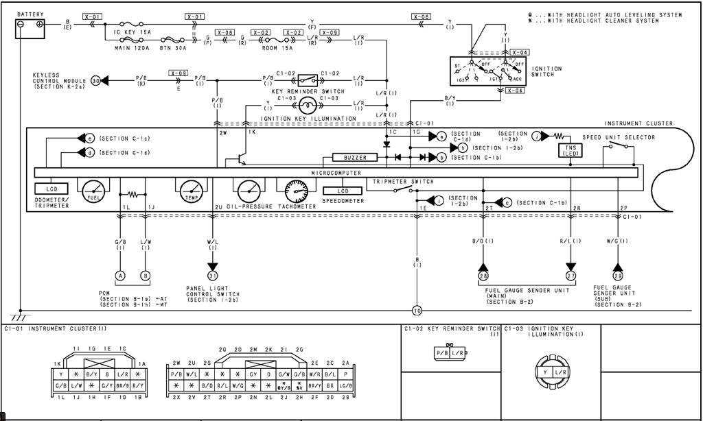
I’ve mentioned in previously to people that the odo requires a state change to update and I think this is why people haven’t been able to identify what controls it – simply writing a value doesn’t do anything. It is controlled via byte 1 of what I defined as statusMIL, this is CAN ID 0x420 which is the same ID which also controls things like the temperature and oil pressure displays on the dash.

I originally identified how this was controlled during some of my early reverse engineering work on the cluster when I was just sending blocks of values (initially cycling between 00 and FF for all bytes in the array) to CAN ID’s to see if I could make anything happen and I noticed at some stage the trip had increased. Clearly this meant one of the ID’s was doing something and because the same ID also controls various warning lights they also flashed on and off at the same time as the odo incremented which made the identification of the ID rather simple.

Next up I edited the program to count each byte in the CAN data up in order, so for example start with an array with only 00 in each byte then starting at byte 0 increment the value by 1, send the whole array, wait briefly and increment again and so on. When the top value of FF is reached set it back to 00 step on to byte 1 and so on. This allowed me to isolate the specific byte that was controlling the odo changes. Anyway the story goes on and after a lot of trial and error with values and timings I got to this bit of fairly horrible test code:

#include <mcp_can.h>
//#include <mcp_can_dfs.h>      //Declaration for Standard Can
#include "mcp2515_can.h"        //Declaration for Seeedstudio Can Library

#define CANint 7  // Normally 2
#define LED2 23   // Normally 8
#define LED3 0    // Normally 7

#define NOP __asm__ ("nop\n\t")
const int SPI_CS_PIN = 17;
mcp2515_can CAN0(SPI_CS_PIN);   // Declaration for Seeedstudio library
//MCP_CAN CAN0(SPI_CS_PIN);     // Set CS to pin 10 - Older Library version


void setup() {
  Serial.begin(115200);

    delay(1000);    //delay to allow for monitor
    Serial.println("Init…");
    Serial.println("Setup pins");
    pinMode(LED2, OUTPUT);
    pinMode(SS, OUTPUT);
    pinMode(LED3, OUTPUT);
    pinMode(CANint, INPUT);

    Serial.println("CAN init:");
    
    if (CAN0.begin(CAN_500KBPS) == CAN_OK) 
    {
        Serial.println("OK!"); 
    } 
    else 
    {
        Serial.println("fail :-(");
        while (1) 
        {
            Serial.println("Zzz… ");
            delay(1000);
        }
     }

Serial.println("Good to go!");
}

unsigned char statusPCM[8]  = {125,0,0,0,156,0,0,0};                            // Write to 201
unsigned char statusMIL[8]  = {140,0,0,0,1,0,0,0};                              // Write to 420

void loop() 
{
    
    unsigned int i=0;
    unsigned int j=0;
    unsigned int k=0;
    float mile=0;
    unsigned char num;


    //Warning Lights - 0=Error, 1=OK

        for(k=0;k<200;k++)
        {
          
          for(i=0;i<=206;i++)
          {
          
          statusPCM[0] = 50;           //RPM  Value*67 gives 8500 RPM Reading Redline is 127
          statusPCM[1] = 0;           
          statusPCM[2] = 0;
          statusPCM[3] = 0;
          statusPCM[4] = 93;           //Speed  Value=0.63*(Speed)+38.5
          statusPCM[5] = 0;
          statusPCM[6] = 0;
          statusPCM[7] = 0;

          statusMIL[0] = 145;         // Temp 91-0%; 96-10%; 107-25%; 152=50%; 158-75%; 164=100%    
          statusMIL[1] = i;           // Odo / Trip     
          statusMIL[2] = 0;
          statusMIL[3] = 0;
          statusMIL[4] = 1;           // Oil Pressure (0=Off, >=1 is OK)         
          statusMIL[5] = 0;           // Check Engine Light
          statusMIL[6] = 0;           // Battery Charge Light
          statusMIL[7] = 0;
          
            CAN0.sendMsgBuf(0x420, 0, 8, statusMIL);
            delay(20);
            CAN0.sendMsgBuf(0x201, 0, 8, statusPCM);
            delay(20);
          }
          
        Serial.println("Miles : ");
          mile=(k+1)*0.05;
          Serial.println(mile);
      
        } 
while(1){}
}

Basically much of it is the includes and setup which is common on all CAN code but the more interesting bit is the main loop. In essence it just uses two nested loops to count up to a certain value and transmit the new value each time. All the other CAN is just static values to turn off warning lights on the cluster – the the ID 201 isn’t actually required here but it stops extra things blinking at you! Additionally ignore the comments on the statusPCM, while these sort of work I realised later that the speed and RPM use 2 byte blocks rather than a single byte to display all values.

So in the code there are 2 loops, the first is counter “i” which in this counts up to 206 (which is 207 steps including 0) and the second outer loop “k” which counts up to 200 and for each increment of “i” the new byte value is sent over CAN. Now through experimenting with various values for counters in earlier versions of this code I’d come up with the values you see here which seem to be consistently accurate for me. Basically 207 changes of the byte sent to the dash = 0.05 Miles counted so the extra loop “k” multiplies this up to a useful mileage change we can measure on the cluster. every time “k” increments it also sends and update to the serial monitor so we can keep track of it. We can see that 200 loops of 0.05 miles should result in a count of 10 miles and that’s exactly what we get on the trip meter.

The very last line is one you don’t see in many Arduino programs, “while(1){};” makes the program hang at this step. Basically what it’s doing is a normal while loop except using a static 1 as the condition makes it always true but there’s no code in the curly brackets so it will just sit there endlessly doing nothing rather than starting the main loop again as it would normally. This was simply so I could leave the code running to completion (at this stage I was sending CAN data with much wider time delays than needed to make sure none got missed) without it looping back round without me noticing.

So now we can count it up which is interesting but not especially useful as it is but since my car didn’t move I left it here for a long time with the plan to sort it out later. Anyway following my recent posts resurrecting this project there’s been some interest in how to sort it out so I started working on it within my already butchered about derivative of Dave Blackhursts code, which in itself was a further development of much of my earlier work. I’m aiming to post a version of my finalised code for the complete system once I’m happy I’ve got all the features I want but this should give you enough info to understand how this bit works.

Updates by Timer1 Interrupt

First off lets just say this didn’t work quite right for this task so I moved away from timer interrupts but it does include some interesting bits of timer manipulation so I’m including it anyway.

The best idea I had initially was to use the data from the ABS system which gave an accurate speed for all the wheels individually but the problem was I would need to vary the frequency at which the ODO byte was changed such that the ODO rate matched the speed. My first idea here was to use a hardware timer on the Arduino and use a hardware interrupt to increment and send the CAN packet. This would require the timer count value to be calculated on the fly from the ABS data. First I built and Excel spreadsheet which firstly calculated the frequency we need to update and send CAN data at to give the right ODO reading for a given wheel speed.

excel mph to freq conversion

So all this does is some basic calculation,

Pulses per mile * mph = pulses per hour

pulses per hour / 3600 = Hz (updates per second)

1000 / Hz = Millisecond interval per update (used to cross reference from the CAN logger)

From this we can fiddle about with values to see what gives enough range on timer1 (because it’s 16 bit which gives us a much wider range of intervals, timer 0 is only 8 bit and usually used elsewhere in the Arduino IDE) to make this work, or for that matter if it even is possible without dynamically changing the pre-scaler value.

Timer 1 is controlled primarily by register OCR1A which is the value it counts to before the timer resets so we need to work out the correct value for the register to do what we want. Rearranging the standard equation gives us this:

OCR1A = (( Clock_Freq / Required_Freq ) / Prescale ) – 1

Now because the count is a 16 bit integer there will be some error created by rounding on the count value so I added another section which updates to show the error vs the required value.

Excel OCR1A count value calculation

The top two lines are just the standard calculation the middle two lines are where the clock and prescaler values are entered and the OCR1A value is calculated. The 230 and 1.15 come from the previous step automatically. The bottom two lines then return the degree of error resulting.

It looks like we can cover the range we want with a prescaler of 1024 however as the speed goes down below 1mph the period between CAN sends becomes excessively long and beyond the range of the timer (max value of OCR1A is 65535), the limit is approximately 0.21 mph which seems reasonable. This means only 1 update over CAN every 4.1s which it turns out is about the limit anyway because if you make the updates longer than about 4.5s for this ID all the warning lights turn on again between updates but we can handle this case seperately.

Now to get the timer working we need to set up a few other things

TCCR1B options

We want to use CTC mode resets the count value at the top of the count to make it loop round constantly so WGM12(CTC1) in register TCCR1B should be set to 1.

TCCR1B options

Next to get the prescaler value of 1024 we need we set CS12 and CS10 to 1. Lastly OCIE1A in TIMSK1 needs to be set to 1 to trigger the interrupt every time the count reaches the count value set bring it all together and we get something like this :

void setupTimer1() {
  noInterrupts();
  // Clear registers
  TCCR1A = 0;
  TCCR1B = 0;
  TCNT1 = 0;

  // Freq (Hz) (Clock (Hz) /((OCR1A + 1) * Prescaler))
  OCR1A = 64700;
  // Set CTC mode - trigger interrupt on TOP
  TCCR1B |= (1 << WGM12);
  // Prescaler 1024
  TCCR1B |= (1 << CS12) | (1 << CS10);
  // Output Compare Match A Interrupt Enable
  TIMSK1 |= (1 << OCIE1A);
  // Enable Interrupts
  interrupts();
}

// Send update to cluster on interrupt
ISR(TIMER1_COMPA_vect) {
    // Increment ODO byte each time function is called
  // this makes ODO update based on ISR frequency call.
  // Check speed is > 0.21 mph ( (left+right/2) * 0.337962 * 100
  if ( (frontLeft + frontRight) >= 68){
    send420[1]++;   
  }
   
  CAN0.sendMsgBuf(0x420, 0, 7, send420);
 
  return;
}

Next up to convert from a speed to a timer count value we need to do the same thing on the Arduino that we did in Excel earlier so here’s a quick function which just calculates count.

int calcTimer1Count(float speedKMH){
  float freq;
  int count;
  float speedMPH;
  
  //Serial.print("speed = ");
  //Serial.println(speedKMH);
  speedMPH = speedKMH / 160.934;
  // Required frequency for timer 1 ISR
  //  1.15 is 4140 (Pulse per Mile) / 3600 (1hr in seconds)
  //  0.7146 is 2572.5 (pulse per KM) / 3600
  freq = speedMPH * 1.15; 
  //Serial.print("freq = ");
  //Serial.println(freq);
  // Required OCR1A value based on 16Mhz clock, works best with 1024x prescaler giving minimum 0.21mph
  count = ((16000000 / freq) / 1024) - 1;
  //Serial.print("count = ");
  //Serial.println(count);
  return count;
}

The input here is km/h because that’s what the ABS values are given in so we might as well convert that here as well.

Now in the main loop we’re scanning for incoming data on CAN and checking what the ID is already for the bits to manage the immobiliser exchange and handily in this Dave Blackhurst has already added code to read the ABS data which we know is coming in on ID 4B0 in two byte blocks so we can just update OCR1A with a function call to our new calculation function with the average of the front wheel speeds whenever new ABS data is received.

    if(ID == 0x4B0) {
      frontLeft = (buf[0] * 256) + buf[1] - 10000;
      frontRight = (buf[2] * 256) + buf[3] - 10000;
      rearLeft = (buf[4] * 256) + buf[5] - 10000;
      rearRight = (buf[6] * 256) + buf[7] - 10000;
      
      //Going to check front wheel speeds for any issues, ignoring the rears due to problems created by wheelspin
      if (frontLeft - frontRight > 500 || frontLeft - frontRight < -500) { //more than 5kph difference in wheel speed
        checkEngineMIL = 1; //light up engine warning light and set speed to zero
        vehicleSpeed = 0;
      } else {
        vehicleSpeed = (((frontLeft + frontRight) / 2) / 100); //Get average of front two wheels.
      }
      //Update timer count value with live speed for ODO
      OCR1A = calcTimer1Count((frontLeft + frontRight) / 2);
      
      // Dump speed to serial for debug - this is just a cropped int.
      //Serial.println(vehicleSpeed);
      
    }

Now when I ran the whole program I hit a minor issue, it worked initially and the timer speed changed correctly but after a small number of can packets the Arduino stopped sending any other CAN data. I don’t know what caused it – best guess is when the interrupt was called it was blocking something and causing a buffer overrun somewhere else making the Arduino crash but either way I felt a different approach would probably be quicker than solving that so I moved on.

Updates by Delay

So the alternate approach relies on the main loop running quite quickly and simply counts how much time has elapsed since a function was last called and if over the set value calls the function. This basically allows functions to be called in the loop without needing to slow the loop itself down. The down side here vs interrupts is the accuracy of this is entirely based on the speed of the main loop so if the loop slows down the events will move about in time. Also obviously if the loop is only doing something like 10ms per iteration you will never get something to go faster than that!

void loop() {
  //Send information on the CanBus every 100ms to avoid spamming the system.
  if(millis() - lastRefreshTime >= 100) {
    lastRefreshTime += 100;
    sendOnTenth();
  }

So this is the initial version Dave used in his code to keep the scanning at a decent pace for the CAN reads. The function millis() just returns a counter value in milliseconds since startup. Unfortunately scanning at millisecond rates isn’t going to cut it for the ODO because at say 200mph the update period is 4.35ms so if we work in ms the best we could do assuming the loop ran fast enough is 5ms which means the ODO would be going 15% slower than the vehicle speed. Luckily Arduino also has a similar built in function ‘micros()’ which does the same thing but counts in microseconds. Some of you familiar with binary might be thinking an integer counting up in microseconds will hit its limit very quickly and then it is likely to cause a problem with the calculation however we get round this because the returned value is of type ‘unsigned long’ which gives us a range of up to about 70 minutes before the count resets. Interestingly because of the way data types wrap round like this the variable “lastRefreshTime” can actually be either signed or unsigned and it works the same.

long calcMicrosecODO(float speedKMH){
  long uS;
  float freq;
  float speedMPH;
   
  Serial.print("Speed = ");
  Serial.print(speedKMH/100);
  Serial.println(" km/h");
  speedMPH = speedKMH / 160.934;
  // Required frequency for timer 1 ISR
  //  1.15 is 4140 (Pulse per Mile) / 3600 (1hr in seconds)
  //  0.7146 is 2572.5 (pulse per KM) / 3600
  freq = speedMPH * 1.15; 
  Serial.print("Freq = ");
  Serial.print(freq);
  Serial.println(" Hz");
  uS = 1000000/freq;
  if(uS < 4500000 && uS > 0){
    return (uS);}
  else {
    return (4500000);
  }

Similarly to the previous interrupt version we have a function which calculates the correct delay required to keep the ODO at the right frequency, there are some minor differences to work in microseconds and if the speed is too slow cap the output at 4500000us (4.5s). Otherwise it’s much the same.

    if(ID == 0x4B0) {
      frontLeft = (buf[0] * 256) + buf[1] - 10000;
      frontRight = (buf[2] * 256) + buf[3] - 10000;
      rearLeft = (buf[4] * 256) + buf[5] - 10000;
      rearRight = (buf[6] * 256) + buf[7] - 10000;
      
      //Going to check front wheel speeds for any issues, ignoring the rears due to problems created by wheelspin
      if (frontLeft - frontRight > 500 || frontLeft - frontRight < -500) { //more than 5kph difference in wheel speed
        checkEngineMIL = 1; //light up engine warning light and set speed to zero
        vehicleSpeed = 0;
      } else {
        vehicleSpeed = (((frontLeft + frontRight) / 2) / 100); //Get average of front two wheels.
      }
      //Update timer count value with live speed for ODO
      ODOus = calcMicrosecODO((frontLeft + frontRight) / 2);
      
      Serial.print("ODO Step : ");
      Serial.print(ODOus);
      Serial.println("us");
      // Dump speed to serial for debug - this is just a cropped int.
      //Serial.println(vehicleSpeed);
      
    }

Above we see the call for ‘calcMicrosecODO’ which is basically the same as the interrupt version but gives an actual time delay in microseconds rather than a timer count. It is called in this way with a calculation in the parameter field because if it is stored in a variable in between the number gets cropped off at the decimal point even if the variable is a float – I believe this is due to the way Arduino processes floats.

void loop() {
  //Send information on the CanBus every 100ms to avoid spamming the system.
  if(micros() - lastRefreshTime >= 100000) {
    lastRefreshTime += 100000;
    sendOnTenth();
  }
  // Call function to updateMIL on variable timebase
   if(micros() - ODORefreshTime >= ODOus) {
   ODORefreshTime += ODOus;
    sendOnClock();
  }

So our extra call for the variable timed refresh is above, it varies a bit from the first one because we have a varying time delay depending on the frequency required which here is a long we are calling ‘ODOus’ which we calculated previously. Obviously because we are using two comparisons we need another refresh time variable to keep them distinct, this is also a long. Also the second one calls a specific function for the variable time refreshes ‘sendOnClock()’

void sendOnClock(){
  // Do not increment ODO byte when step is = 4.5s
  // slower than this updateMIL must still be called so 
  // warning lights don't turn on but speed may be zero!
  if ( ODOus < 4500000){
    send420[1]++;   
  }
  updateMIL();
  CAN0.sendMsgBuf(0x420, 0, 7, send420);
}

This function is pretty basic, all it’s doing is checking the resulting ODOus value isn’t 4.5s because if it is this value is means the calculation is at it’s upper limit and the car isn’t moving (specifically the speed is below 0.21 mph). In this state it still updates the warning light registers and sends the CAN packet to keep the warning lights from blinking on but it doesn’t increment the ODO byte value so the ODO doesn’t continue to tick on.

// Time delay for Odo
long ODOus = 4500000;      

// Set to max 4,500,000 to keep dash 
// MIL warning lights awake at 0 speed

The declaration for ODOus is set as 4,500,000 at start up so it correctly. The only downside to this is it takes a few seconds for the dash lights to go out initially and the oil pressure gauge goes to normal in two steps. This could be dramatically improved either by setting a higher minimum speed at which the ODO ticks because even increasing to 0.5 mph would improve the maximum duration to 1.7 seconds. Another option to avoid this is just to send an update to 0x420 in between the ODO calls. If we keep the one to the other loop ‘sendOnTenth’ without incrementing the ODO value it will just display any changes to the warning lights almost instantly while keeping the ODO working correctly.

void sendOnTenth() {
  //  PCM Status's to mimic the PCM being there, these may be different for different cars, 
  //  and not all are always required, better safe and include them all.
  CAN0.sendMsgBuf(0x203, 0, 7, send203);
  CAN0.sendMsgBuf(0x215, 0, 8, send215);
  CAN0.sendMsgBuf(0x231, 0, 8, send231);
  CAN0.sendMsgBuf(0x240, 0, 8, send240);
  CAN0.sendMsgBuf(0x620, 0, 7, send620);
  CAN0.sendMsgBuf(0x630, 0, 8, send630);
  CAN0.sendMsgBuf(0x650, 0, 1, send650);
  
  updateMIL();
  CAN0.sendMsgBuf(0x420, 0, 7, send420);    // Duplicated in sendOnClock to update ODO

  updatePCM();
  CAN0.sendMsgBuf(0x201, 0, 8, send201);

So that’s it but I should probably mention that I’ve not tested this on a live car however I have a program which works out the correct CAN byte values and then builds a correctly formatted string which can be pasted into USBtinViewer and sent to simulate an update from the ABS and the Arduino and cluster all seem to respond correctly:

Labview speed to CAN bytes converter  front panel
Labview speed to CAN bytes converter  front panel code

In this code you will see a scaling factor of 100 which should be correct but on my cluster I seem to get a speedometer reading 1 mph higher than intended from a calculated 5-185mph I actually see 6-186 mph on the cluster. I’m not sure why this is but it may be on purpose due to the common requirement for speedometers to never read lower than true speed. Indicated speed is required to be within -0% / +10% + 4km/h of actual speed in the EU. Technically we could correct this by doing two vehicle speed calculations on the Arduino, one for the odometer calculation using the proper scaling factors to keep it accurate and one for the displayed vehicle speed using a scaling factor which corrects this error. I do not intend to do this but I have found a scaling factor of 99 rather than 100 makes the speedometer match up if required.

As ever your mileage may vary, but hopefully it’ll closer than it was before! As I said earlier this is part of another major overhaul of the code and I’m intending to publish the final version as a complete code when I’m happy I’ve got everything working but that might take some time.

RX8 Project – Part 13, Canbus #3, Labview!

If you just want the CANbus ID for the RX8 PS light and not all the background work just skip to the end!

So it’s been quite a long time since I had chance to have another go at getting the CANbus on the cluster working and while previously I manged to get everything apart from the power steering warning light working I decided I really should find out why not. This is a simple lesson in why getting sufficient sleep is really important!

I was contacted a while ago buy a guy doing a similar conversion to mine who happened to have a second complete RX8 and a variety of diagnostic equipment that can talk CANbus who had send me a block of CANbus log data that I’ve done nothing like enough work on since I’ve had it! Anyway the key here is I knew that the car some of the logs had come from had the factory PCM (ECU) working as intended and as such the power steering light doesn’t illuminate. This meant that somewhere in that log file was the data that turned off the light, I just had to work out where it was!

Now first off I took the approach of taking the two sets of data logs I had, one from a car with a functioning PCM and one from a car that doesn’t. Then list out all the ID’s that occurred in each set of data. I’m going to assume for my purposes that any that occur in both sets are not required. The logic being that the data that turns off the light must be present in one set and not the other. I admit that this might not be the case if there’s something more complex going on like if with the PCM removed the power steering computer doesn’t get the required data and sends a different value on the same ID. But for now it’s a starting point!

The ID’s that remain are as follows:

201, 203, 215, 231, 240, 250, 420, 620, 630, 650

A couple of these we’ve already seen elsewhere, specifically 201, which is the RPM and speed to the dash, and 420 which control the cluster warning lights. So after setting up the arduino and canbus data to strobe all these remaining address and nothing happening I gave up!

Many weeks went by and I it was nagging at me why I couldn’t find the right code. Eventually I decided to try a different tack so I ordered a USBtin which is a really neat little USB to CAN adapter which appears as a virtual COM device in windows and can be controlled using a series of commands known as the LAWCIEL protocol (details of which can be found here). The kit version is really quite cheap and would probably be a good option for the budget conscious but on this occasion I just decided to be lazy and buy the prebuilt one.

Clearly I’ve decided to PC control it at this point! Next up I needed a way to stop it when the warning light went off. I ordered a very cheap optical detector off ebay which can be wired into an Arduino or something similar. These are the ones that vary around £1-2  so difficult to argue with. They offer a potentiometer to adjust the switching brightness so I can tune it to what I need and a digital output so I don’t need to mess about doing analog reads or calibrating things on a microcontroller. Yes i know it’s not the neatest or most efficient way of doing it but for my purposes it’s so cheap and easy it really doesn’t matter! So I need to make that talk to a PC in a way I can use and that’s where this whole thing starts to get more interesting.

I’d pondered ways of interfacing a microcontroller to a PC easily and while it’s not terribly hard to make it shout over serial when an input goes high I came across something much more interesting. There’s a company called National Instruments who make lots of very expensive software and equipment for recording data from experiments but fairly recently they started supporting hobbyists by producing the Labview Makerhub, and more specifically a package called LINX. LINX includes a series of drivers and firmwares to allow things like Arduinos, Beaglebones and even Raspberry Pi’s to be used as IO devices (the Raspberry Pi can actually have programs loaded to them as a full remote node). This is quite a major step because it suddenly allows hobbyists to use really good professional software without having the problem of only being able to use NI’s extremely expensive hardware! This gave me and idea – use labview as the core software then I can use the supplied LINX firmware to set up an arduino as IO. To make this deal even sweeter you can also download Labview for free from NI for home use. Take a look here

So after a quick bit of following the instructions we have a basic labview program that will read the arduino IO via serial:

Labview Lynx1

Basically what this does  is it starts by opening a serial connection via the LINX toolkit, this returns a device name to an on screen string display and passes a reference which identifies the connection to the read stage. The next bit the larger grey rectangle is how Labview handles a while loop so it’ll keep performing the enclosed functions constantly from left to right until the conditional term in the bottom right goes high – in this case it’s a stop button. So basically the loop just calls a LINX channel read of channel 2 where I connected the light sensor to the Arduino. The inner rectangle only executes when the read value is false (i.e. when the light goes off) and while there’s a lot of information recorded here from elsewhere in the program basically if it sees the light go off it records the current ID being tested, the time that has elapsed since the test started. This means we know when it’s right!

Labview is designed to capture data from lab instruments and so there’s a really handy thing called the VISA toolkit that allows blocks of data read and write via the serial port and basically you can just open a port with specified settings then make read and write requests and do things like crop the incoming data at a predefined character. In this case that character needed to be CR (Carriage Return) this is ASCIIcharacter 13 because LAWCIEL terminates everything with one.

Labview Lynx2

For the USBtin we open the correct COM port at 115200,8 Data bits, No parity, 1 stop bit and no flow control. The other thing to note is at the top right, this sets the termination character to the numeric value of CR, the benefit here is you can perform a read of any length and it will automatically break up the data in the buffer so a single read can vary in length but the start will always synchronise  with the read call. Opening the connection in a terminal program for the first time and you’ll see nothing actually happens as such, an OK is signified by a CR so all you see is the cursor move. At this stage we are only connected to the USBtin, not the CANbus. So next, configure the CAN connection, send a value of “S6\r” . The code is S6, this will set the USBtin to 500kbit correct for the dash, the \r is how you indicate a CR in a Labview string. Next I chose to send “v\r” which requests the version from the USBtin, we don’t need this but it gives a solid confirmation it’s talking to us. Next up Z1\r tells the USBtin to timestamp the incoming data, I thought this might be useful but never actually implemented it.

Labview Lynx3

With the setup complete we can start reading data by opening the CAN connection by sending O\r. On a terminal program (assuming you have the CANbus wired up) doing this would result in packets of can data from the cluster appearing. The initial read of length 1 byte reads just the confirmation from the USBtin that it has received the open request. Next is the main read, it’s worth noting the read length is set at 50 bytes but this will be cut short by the termination character set earlier so we can accept varying length CAN data. C\r closes the CAN connection and again another read 1 byte clears the acknowledge. Tacked on the end is a section to read the controller status looking for error states etc. The keen eyed amongst you will notice the majority of this code is conditional, this is because the code needs to insert send requests among the stream of reads. This is because if the data is not read from the USBtin constantly a buffer somewhere fills (I imagine on the USBtin itself but can’t confirm this) and the port crashes. I spent a lot of time finding this out the hard way!

Labview Lynx4This is the write data code, again very similar but it just opens the port, writes whatever string is in the buffer and closes the connection. Once the connection is confirmed closed it resets the Boolean that causes the ‘write’ condition so on the next loop it goes back to reading again to keep the buffer clear. The read loop runs at the maximum possible speed but it is slowed down because it waits for either a termination character or 50 characters to be received before it completes and loops again.

Beyond that the only other bits of code just generate the data for the write buffer using an increment counter for the ID field and toggling between either 8 bytes of FFFF or 0000 every 100ms for 20 cycles and setting the write flag high to send the data..

So after letting this run for a fair while it started spitting out values, specifically the ID 300 for the power steering light. Wait a minute that wasn’t in the list earlier. Yes I know that, that’s where getting enough sleep comes in. Originally I split the data based on whether or not the PCM was fitted and ignored the ones that occurred in both sets, the obvious mistake here is that of course the power steering light isn’t controlled by the PCM, quite logically it’s controlled by the power steering controller!

So there we go, ID 300, the first byte (leading) controls the light, values below 80 turn the light off. Unplugging the PCM causes the controller to send 80 on loop hence the the warning light.

Get data from ID: 4B1
0	0	0	0	0	0	0	0	
-----------------------------
Get data from ID: 81
43	6F	1	4B	
-----------------------------
Get data from ID: 300
80	
-----------------------------
Get data from ID: 231
F	0	FF	FF	0	
-----------------------------
Get data from ID: 430
95	5F	83	0	0	0	60	
-----------------------------
Get data from ID: 81
25	6F	1	4B	
-----------------------------
Get data from ID: 81
16	6F	1	4B	
-----------------------------
Get data from ID: 630
8	0	0	0	0	0	6A	6A

Looking at the log data again we see that ID 300 is getting a value of 80 – this is during the self test before the engine is started. I previously tried sending this data on the original Arduino CAN setup and go no result so what did I do wrong. Again this is based on another assumption, I though the logger was ignoring high order bytes with zero value (ie this value if could be 00-00-00-00-00-00-00-80) well it turns out that was totally wrong, it actually ignores trailing zeros, the value of the can data here should be 80-00-00-00-00-00-00-00.

So while all these hours of work told me one thing I should have already known it’s actually worked out Ok because it highlighted this other problem (read ‘incorrect assumption’ !). This means The odds of me working out all the other data from the logs (that I’d previously written off as not usable) is actually much higher!


RX8 Project – Part 6, Canbus #2

So now we have a powered up RX8 cluster and some Canbus hardware that we can talk to we can start doing a few interesting things with our new setup.

Fire up the Arduino IDE and we can start writing our basic controller code. Canbus devices have a device address and a memory location for all the required data so we need to work all of these out. This is a lot easier for digital IO than the more complicated analog values because digital IO are just either set bit on or off whereas analog values can have funny scaling and things going on. I initially used a canbus demo program which worked because I basically cloned the Arduino Canbus shield. Plenty of starter guides and information can be found here : https://learn.sparkfun.com/tutorials/can-bus-shield-hookup-guide

My initial approach involved setting the target address for the Canbus transmission and sending patterns of bits high and low and see what happens. Google told me that the cluster Canbus interface operates on 500 kHz clock so with that information we should get a connection.

#include <Arduino.h>
#include <mcp_can.h>
#include <mcp_can_dfs.h>

#define CANint 2
#define LED2 8
#define LED3 7

MCP_CAN CAN0(10); // Set CS to pin 10

void setup() {
 // put your setup code here, to run once:
 Serial.begin(115200);
 Serial.println("Init…");

Serial.println("Setup pins");
 pinMode(LED2, OUTPUT);
 pinMode(LED3, OUTPUT);
 pinMode(CANint, INPUT);

Serial.println("Enable pullups");
 digitalWrite(LED2, LOW);
 Serial.println("CAN init:");
 
 if (CAN0.begin(CAN_500KBPS) == CAN_OK) 
 {
 Serial.println("OK!");
 } 
 else 
 {
 Serial.println("fail :-(");
 while (1) 
 {
 Serial.print("Zzz… ");
 delay(1000);
 }
 }

Serial.println("Good to go!");
}

unsigned char offarray[8] = {0, 0, 0, 0, 0, 0, 0, 0}; // Always Off Array
unsigned char onarray[8] = {255,255,255,255,255,255,255,255}; // Always On Array

void loop() {
 // put your main code here, to run repeatedly:

for (int i=0; i <= 512; i++){ 
  for (int l=0; l <= 10; l++){  
    for (int j=0; j <= 100; j++){
       CAN0.sendMsgBuf(i, 0, 8,offarray);
       delay(10);
     }

     for (int k=0; k <= 100; k++){
     CAN0.sendMsgBuf(i, 0, 8,onarray);
     delay(10);
     }
   }
  }
}

So this loop will iterate through 512 addresses strobing all 8 bytes high and low on 1 second intervals. The trick here is that canbus needs regular packets to stay active, so we can’t just send a value once. In this case each value (high or low) is send 100 times at 10ms intervals so the cluster should stay active long enough to see if anything is happening. Each address will get 10 cycles of high and low before moving onto the next address. In concept this would work and provided ‘i’ is set to increment high enough you would cover all the addresses. Bear in mind at this rate you’d have to watch it for about 90 mins…

Thankfully around the time I started running though this trying to find any useful addresses I came across this :

https://www.cantanko.com/rx-8/reverse-engineering-the-rx-8s-instrument-cluster-part-one/

This nicely tied in with the hardware I was working on and so the code and information is all exceedingly useful and saved me a lot of time. Specifically it gives the address locations for most of the indicators on the cluster which is what we really need.

After lots of trial and error I managed to come up with a block of code that can control the cluster but easily allow me to set any warning light I need on the dash, or more accurately also to turn off all the warning lights. Something that will be essential come MOT time as a warning light that stays on is an MOT fail and since most of the systems that control them will no longer be in the car (primarily the original ECU).

#include <Arduino.h>
#include <mcp_can.h>
#include <mcp_can_dfs.h>


#define COMMAND 0xFE
#define CLEAR 0x01
#define LINE0 0x80
#define LINE1 0xC0

#define CANint 2
#define LED2 8
#define LED3 7

#define NOP __asm__ ("nop\n\t")

// Variables for StatusMIL
bool checkEngineMIL;
bool checkEngineBL;
byte engTemp;
byte odo;
bool oilPressure;
bool lowWaterMIL;
bool batChargeMIL;
bool oilPressureMIL;

// Variables for PCM
byte engRPM;
byte vehicleSpeed;

// Variables for DSC
bool dscOff;
bool absMIL;
bool brakeFailMIL;
bool etcActiveBL;
bool etcDisabled;


MCP_CAN CAN0(10); // Set CS to pin 10

void setup() 
{
    
    //Serial.begin(115200);
    //Serial.println("Init…");
    //Serial.println("Setup pins");
    
    pinMode(LED2, OUTPUT);
    pinMode(LED3, OUTPUT);
    pinMode(CANint, INPUT);

    //Serial.println("Enable pullups");
    digitalWrite(LED2, LOW);
    //Serial.println("CAN init:");
    
    if (CAN0.begin(CAN_500KBPS) == CAN_OK) 
    {
        //Serial.println("OK!");
    } 
    else 
    {
        //Serial.println("fail :-(");
        while (1) 
        {
            //Serial.print("Zzz… ");
            delay(1000);
        }
     }

Serial.println("Good to go!");
}

unsigned char stmp[8]       = {0, 0, 0, 0, 0, 0, 0, 0};                         // Always Off Array
unsigned char otmp[8]       = {255,255,255,255,255,255,255,255};                // Always On Array

unsigned char statusPCM[8]  = {125,0,0,0,156,0,0,0};                            // Write to 201
unsigned char statusMIL[8]  = {140,0,0,0,0,0,0,0};                              // Write to 420
unsigned char statusDSC[8]  = {0,0,0,0,0,0,0,0};                                // Write to 212

unsigned char statusEPS1[8] = {0x00,0x00,0xFF,0xFF,0x00,0x32,0x06,0x81};        // Write to 200 0x00 00 FF FF 00 32 06 81
unsigned char statusEPS2[8] = {0x89,0x89,0x89,0x19,0x34,0x1F,0xC8,0xFF};        // Write to 202 0x89 89 89 19 34 1F C8 FF

unsigned char statusECU1[8] = {0x02,0x2D,0x02,0x2D,0x02,0x2A,0x06,0x81};        // Write to 215 - Unknown
unsigned char statusECU2[8] = {0x0F,0x00,0xFF,0xFF,0x02,0x2D,0x06,0x81};        // Write to 231 - Unknown
unsigned char statusECU3[8] = {0x04,0x00,0x28,0x00,0x02,0x37,0x06,0x81};        // Write to 240 - Unknown
unsigned char statusECU4[8] = {0x00,0x00,0xCF,0x87,0x7F,0x83,0x00,0x00};        // Write to 250 - Unknown


/*

215 02 2D 02 2D 02 2A 06 81 // Some ECU status

231 0F 00 FF FF 02 2D 06 81 // Some ECU status

240 04 00 28 00 02 37 06 81 // Some ECU status

250 00 00 CF 87 7F 83 00 00 // Some ECU status

*/


void updateMIL()
{
    statusMIL[0] = engTemp;
    statusMIL[1] = odo;
    statusMIL[4] = oilPressure;
    
  if (checkEngineMIL == 1)
  {
    statusMIL[5] = statusMIL[5] | 0b01000000;
  }
  else
  {
    statusMIL[5] = statusMIL[5] & 0b10111111;
  }
   
    if (checkEngineBL == 1)
  {
    statusMIL[5] = statusMIL[5] | 0b10000000;
  }
  else
  {
    statusMIL[5] = statusMIL[5] & 0b01111111;
  }

   if (lowWaterMIL == 1)
  {
    statusMIL[6] = statusMIL[6] | 0b00000010;
  }
  else
  {
    statusMIL[6] = statusMIL[6] & 0b11111101;
  }

     if (batChargeMIL == 1)
  {
    statusMIL[6] = statusMIL[6] | 0b01000000;
  }
  else
  {
    statusMIL[6] = statusMIL[6] & 0b10111111;
  }

       if (oilPressureMIL == 1)
  {
    statusMIL[6] = statusMIL[6] | 0b10000000;
  }
  else
  {
    statusMIL[6] = statusMIL[6] & 0b01111111;
  }
}

void updatePCM()
{
    statusPCM[0] = engRPM;
    statusPCM[4] = vehicleSpeed;
}

void updateDSC()
{       
  if (dscOff == 1)
  {
    statusDSC[3] = statusDSC[3] | 0b00000100;
  }
  else
  {
    statusDSC[3] = statusDSC[3] & 0b01111011;
  }

    if (absMIL == 1)
  {
    statusDSC[4] = statusDSC[4] | 0b00001000;
  }
  else
  {
    statusDSC[4] = statusDSC[4] & 0b11110111;
  }

      if (brakeFailMIL == 1)
  {
    statusDSC[4] = statusDSC[4] | 0b01000000;
  }
  else
  {
    statusDSC[4] = statusDSC[4] & 0b10111111;
  }

     if (etcActiveBL == 1)
  {
     statusDSC[5] = statusDSC[5] | 0b00100000;
  }
  else
  {
    statusDSC[5] = statusDSC[5] & 0b11011111;
  }

    if (etcDisabled == 1)
  {
    statusDSC[5] = statusDSC[5] | 0b00010000;
  }
  else
  {
    statusDSC[5] = statusDSC[5] & 0b11101111;
  }
 

}

void loop() 
{
    // StatusMIL
    engTemp         = 145;
    odo             = 0;
    oilPressure     = 1;    // Either 0 (fault) or >=1 (Ok)
    checkEngineMIL  = 0;
    checkEngineBL   = 0;
    lowWaterMIL     = 0;
    batChargeMIL    = 0;
    oilPressureMIL  = 0;

    updateMIL();
    CAN0.sendMsgBuf(0x420, 0, 8, statusMIL);
    delay(10);


    // StatusPCM
    engRPM          = 60;    // RPM  Value*67 gives 8500 RPM Reading Redline is 127
    vehicleSpeed    = 93;    // Speed  Value=0.63*(Speed)+38.5

    updatePCM();
    CAN0.sendMsgBuf(0x201, 0, 8, statusPCM);          //CAN0.sendMsgBuf(CAN_ID, Data Type (normally 0), length of data, Data
    delay(10);

    // StatusDSC
    dscOff          = 0;
    absMIL          = 0;
    brakeFailMIL    = 0;
    etcActiveBL     = 0;    // Only works with dscOff set
    etcDisabled     = 0;    // Only works with dscOff set

    updateDSC();
    CAN0.sendMsgBuf(0x212, 0, 8, statusDSC);
    delay(10);

/*
    CAN0.sendMsgBuf(0x200, 0, 8, statusEPS1);
    delay(10);            

    CAN0.sendMsgBuf(0x202, 0, 8, statusEPS2);
    delay(10);    
           
    
    CAN0.sendMsgBuf(0x215, 0, 8, statusECU1);
    delay(10);  

    CAN0.sendMsgBuf(0x231, 0, 8, statusECU2);
    delay(10);  

    CAN0.sendMsgBuf(0x240, 0, 8, statusECU3);
    delay(10);  
    CAN0.sendMsgBuf(0x250, 0, 8, statusECU4);
    delay(10);  

*/
            
 }

This is the current latest version of the code I have, the serial comms section at the start is handy for checking you have a working connection but if you don’t have the serial monitor open it will cause the Arduino to hang at the transmit instruction and not get as far as updating the canbus so I recommend enabling these initially but once you get a working connection comment them back out as above. There are also sections above taken directly from the Cantanko page to deal with the power steering controller and some other bits, I haven’t tried these yes as the cluster isn’t in a car but I plan do so at some stage.

This code has some limitations in this form, basically the warning lights etc are set in the code as static values so this code will just set everything normal and all the lights I have addresses for to off. One particular curiosity is the way the cluster treats the oil pressure value. The data space actually has a whole byte for a value here but the cluster only only has two values despite having an actual gauge, a value of 0 drops the needle to the bottom, a value of 1 or more sets the gauge to normal. My feeling on this is the car was originally intended to have a proper oil pressure transmitter but someone decided it was too expensive and a normal pressure switch was used instead and rather than redesign the cluster they just changed the scaling in the on board microcontroller to behave as described. long term I’d love to mod the cluster to add the analog functionality back in but without the code for the controller this would probably involve disconnecting the original drive to that gauge and adding another Arduino inside the cluster just for driving that gauge. It seems like a lot of work to know oil pressure on a scale of low to high!

The code also sets a speed and RPM however the ODO and trip meters will not increment as it stands – I purposefully left this bit of code out because it’s only really applicable if you’re on an actual car otherwise your cluster will just keep clocking up. The ODO and trips seemed to be the one bit no-one else had managed to do or identify but after quite a few hours of testing  random blocks will various combinations of high and low as well as sending incrementing / decrementing values I noticed my trip meter had actually moved up by 0.1 miles which meant something was working. I eventually managed to trace it to the address listed above. The trick to actually making it work is that the value in the byte is irrelevant to what the cluster displays, so no this doesn’t let you clock it back! What it appears to do is counts the changes to the value so I made it work by setting up a loop of code that keeps changing this value up to a certain number to give a specific distance. Turns out the cluster needs to see 4140 changes per mile. Eventually I plan to tie this in to the speedometer value so only one value needs to be set, by knowing the pulses per mile and the speed we can work out the time delay between each change. As an example at 100mph we need to send 115 changes per second, this is one every 8.7ms which is obviously faster than the loops above and so for speed and accuracy would have to be hardware timed with an interrupt to do the update at the right speed. I’ll probably do an updated version at a later date.

There’s a couple other things I need to sort out, the airbag warning light being the prime one because this is an outright MOT fail. Now in theory when it’s back on the car it should work just fine as the airbag wiring is all there but I figured it was worth working out anyway. So after working through all of the RX8 cluster wiring diagrams (1)(2)(3)(4) I pieced this together :RX8 Cluster Pinout

This covers the majority of everything someone might need to use the cluster on a simulator apart from the fuel gauge. The RX8 fuel gauge is a bit of an oddity because the car uses a saddle shaped fuel tank to allow it to clear the driveshaft and so it has two senders denoted as ‘main’ and ‘sub’.

RX8 Fuel System Senders

Each of these apparently has a resistance value of between about 325Ω at the bottom and 10Ω at the top. There seems to be some questions about how this system works out what to display based on the two sender values and whether it expects to see one remain full while the other empties or something similar. Unfortunately I’ve not played with it much because I’ve don’t actually need to make this work off the car (since the car will have the senders but I can say putting 100Ω a resistor between both 2R-2P and 2R-2T gives a value of about 1/3 of a tank and 9Ω (because I just added a 10Ω on along side the existing 100Ω) across these connections gives a full tank reading  (actually a little above full) so as long as you move both together it works fine, this is ok if all you want to do is get the fuel warning light off for a driving simulator but not that helpful for a single fuel sender conversion which is why most people are interested. If I get chance I’ll investigate further. Also for some reason it takes an absolute age to move up the scale which is a bit unfortunate but I suspect is as intended. At least it should be stable!

All of that leaved us with just one light I can’t get to turn of, the warning light for the electronic power steering. This is controlled via canbus by the look of the circuit diagram but as yet I’ve not found the address for it. If anyone knows the address please leave a comment! Else I will have to go back to either trial and error or the really dodgy backup plan which involves cutting the tracks in the cluster and doubling up on another warning light which isn’t used much! Maybe I should just add another controller in the cluster!

So hopefully that gives you (almost) everything you need to know about making the cluster work! We might get back to mechanical things in the next update…

RX8 Project – Part 5, Canbus

Following the decision to go for the complete engine swap I had the sudden realisation that nothing was going to work on the car because I wouldn’t have the factory engine and so also wouldn’t have the factory ECU and so no engine data and nothing on the instrument cluster. So I needed to come up with a better plan!

Initially I intended to open up the stock instrument cluster and replace the normal controller circuits inside the cluster with a microcontroller (probably an Arduino) with suitable supporting electronics such as motor driver IC’s to control the gauges and small MOSFET’s to switch the warning lights and anything else I needed to get it working. Done in that way I could interface almost anything to the Arduino and make the cluster behave however I wanted.

I started looking into what wiring the cluster had normally to see if I could hack into anything directly and not have to fake signals, say a nice direct tachometer connection I could use, but found that virtually everything on the cluster was controlled via a canbus communications connection and this gave me other ideas.RX8 ClusterFor anyone who doesn’t know canbus is a differential communications interface used in the majority of common cars to connect all the separate devices together. It is what’s called multi drop and as such all the devices are basically just daisychained on a single pair of wires. Complexity is the data is sent to a specific target device based on a device ID which we don’t know and the format the device needs the data in is to give a particular result is entirely up the manufacturer. So for example even if you found the memory location that controls RPM it might be using a single byte (256 possible values) to represent RPM in the range of 0-7500 rpm. This means that each increment would be a step of approximately 30 rpm which would likely not be noticeable. Or they might use two bytes at different addresses which combine to give the value, or something more complicated! Figure it all out and you can directly control the cluster!

The Arduino can be made to communicate with a canbus system with appropriate components added on. These are available as an off the shelf canbus shield and if you’ve not build circuits like this before I recommend that approach but since I have an electronics background I decided to DIY my own and save the money and so I started down the route of designing a canbus interface. I then had another interesting thought, if I had an engine ECU for the new engine it would be transmitting all sorts of data about what it was doing which would normally go to the cluster of the car it was from. I could work out what address it was sending that data too I could read it all. So suddenly one canbus interface grew to a pair of them so I could connect one to the engine ECU and one to the cluster and eventually use the pair of interfaces to bridge the two canbus connections and convert and reformat all the engine data in real time to control the cluster. Sounds simple right!

Based on information found via Google the chips to use seemed to be the MCP2515 transceiver and MCP2551 canbus line driver. Part of the reason behind this was there are well documented libraries available for the Arduino to work with these, plus they are available in DIP packages to make prototyping on stripboard easier!

Sadly I can’t seem to find the original circuit diagram I drew for this but it was closely based on this one (click to enlarge):Arduino MCP2515 Interface

I tend to use Arduino nanos in my projects, they are very small but have a good clock speed and all the handy features you’re likely to need for fairly small IO count projects. Plus you can buy the knock off version on eBay for very little, my last ones were 5 for £12 delivered next day but can be had for less if bought from a Chinese seller but obviously with a much longer delivery. The down side of these is they make them cheaper by not using the proper FTDI branded USB to serial converter chip, instead they use the CH340G which means the driver isn’t included with the normal Arduino IDE and must be downloaded and installed manually. The appropriate driver can be found from a number of sources via Google.

After quite a bit of work I ended up with something that looked a bit like this (ok, exactly this!)

Arduino Canbus adapter top Arduino Canbus adapter bottom

The red and black coloured solder lines are to distinguish the 5V power from the Arduino from everything else to make sure I hadn’t accidentally shorted  it out. Needless to say there’s quite a bit going on on the bottom of this board! The converter board has options for either screw terminal connectors or the 9 way DSUB used for certain applications. I’ve also included options for connecting power into the DSUB if required. On particularly important feature is the termination resistor, this is situated next to the blue jumper, moving the jumper turns this on or off. Canbus must have this termination resistor connected between the two bus wires (called CANL(-) and CANH(+)) at each end of the bus, so if this is an end node on the bus it needs enabling. If it’s being added to the middle of an existing bus it should be disabled. Other keen people will notice there’s only one Arduino slot occupied, this is because by the time I took the photo it had been commandeered for another project but since I was still working with identifying signals in a single bus at a time it didn’t really matter. I did initial test with two Arduinos connected via canbus  with one transmitting and one receiving just to prove the hardware out.

Next up we need to connect the new hardware up to the RX8 cluster. This assumed it is disconnected from the car, if it isn’t you won’t need to tie in power to the cluster but I have no idea how the but will behave in this situation. If you experimenting as I am it’s advisable to disconnect the canbus pins to avoid problems or just disconnect the whole cluster. to make this work we need to use the smaller connector on the back only. In the diagram above you can see the pinout for this, the simple version is :

Upper Row going left to right
Spare
Spare
B/Y – Ignition Switched +12V
B – 0V (PSU Minus)
L/R – Permanent +12V
Spare

Lower Row
G/B – CANL
L/W – CANH
Spare
G/Y – Unknown
BR/B – Unknown
R/Y – Unknown

For testing purposes both +12V can be connected together and any normal 12VDC PSU (cheapo wall wart or anything else you have) can be used. Congratulations, you now have a powered up cluster you can work with!

Things will get technical in the next section Canbus #2